.png)
Welcome,
Date:2023-08-30
keyword: eSurvey, GNSS, AR Stakeout, SurPad, Land Survey
The SurPad V4.2.230713 version adds a new function- AR Stakeout,
which can significantly improve the efficiency of the stakeout. The use of AR
technology ensures that measurements are accurate, and the margins of error are
eliminated. With AR stakeout, land surveyors and farmers can lay out crops or
plants in precise positions, ensuring minimal wastage of resources and
effective land management. AR stakeout also saves time and reduces the need for
manual labor. With AR stakeout technology, land surveyors and farmers can
quickly mark out the boundaries or locations of crops or plants with ease, thus
increasing efficiency and productivity.
There are different AR stakeout methods depending on whether the RTK Receiver has a camera or not. The RTK receiver has a camera that uses AR stakeout by default. When entering the point stakeout interface, first use the handheld camera to stake out the real scene, and then switch to the camera of the RTK receiver for AR stakeout. It an RTK receiver has no camera, enter the common point stakeout interface, and click the button [AR stakeout] to make the handheld camera carry out AR stakeout. The software is connected to the RTK receiver with a camera, and the AR mode can be freely switched under the stakeout settings: use the receiver AR or AR 3D.
Connect the RTK receiver
without a camera to use AR stakeout steps:
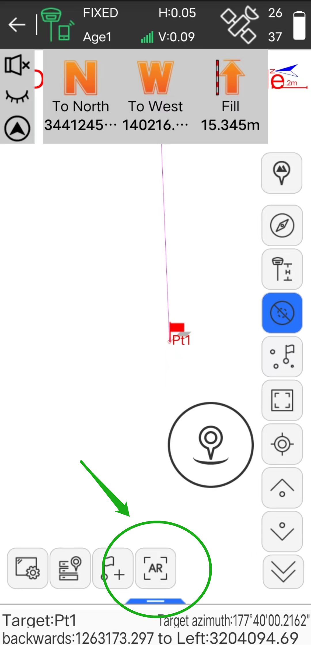
(1) In the stakeout point library, select the target point to carry out the point stakeout interface, and click "AR stakeout" to enter the real scene stakeout.
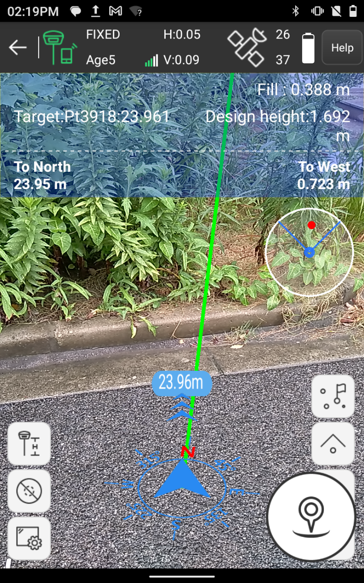
(2) When the distance from the target point is more than 2 meters, it
is the real scene navigation of the handheld camera, and the interface will
display the distance from the current position to the stakeout target point;
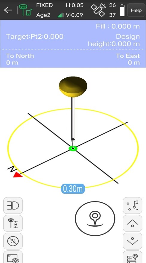
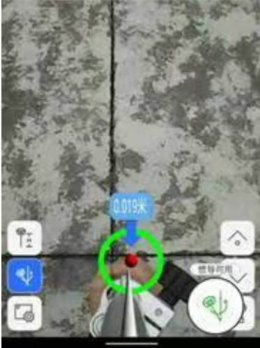
(3) When the distance from the target point is less than 2 meters, it will enter 3D navigation, and the interface will display the relative relationship between the rod tip and the stakeout target point in real-time. If the connected RTK receiver has an inertial navigation function, you can touch the screen to rotate to view the 3D position information from the rod tip to the target point.
(4) Follow the guidance of the
interface to the target point. The interface has reached the stakeout target point,
and the green circle indicates that the stakeout tolerance is less than 0.02
meters. The yellow circle indicates that the stakeout prompt range is less than
2 meters and greater than 0.3 meters. The red circle indicates that the
stakeout tolerance is less than 0.3 meters and greater than 0.02 meters.
Connect the RTK receiver
with a camera to use AR stakeout steps:
(1) In the stakeout point library,
select the target point to perform the point stakeout interface. The AR prompt
range setting of the stakeout receiver is 3 meters, and the stakeout tolerance
setting is 0.02 meters.
(2) When the distance from the target
point is more than 3 meters, it is the real scene navigation of the handheld
camera, and the interface will display the distance from the current position
to the stakeout target point;
(3) When the distance from the target point is less than 3 meters, it will enter the RTK receiver camera navigation, and the interface will display the relative relationship between the pole tip and the stakeout target point in real-time.
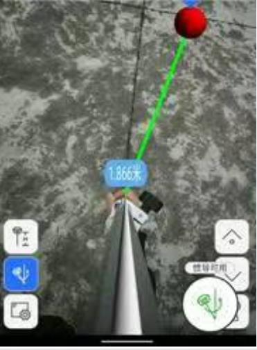
(4) Follow the guidance of the interface to the target point. As shown in the Figure below, the interface has reached the stakeout target point, and the green circle indicates that the stakeout tolerance is less than 0.02 meters.

 eRTK10 mini
 eRTK10
 eRTK20
 eRTK30
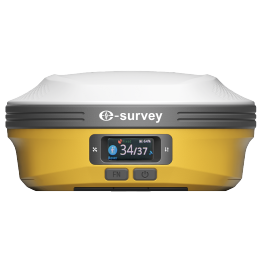 eRTK60
 eBase 20
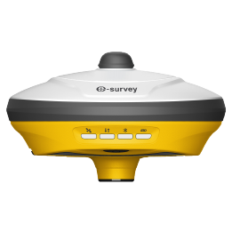 E200
E200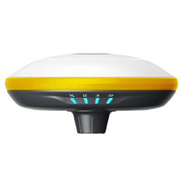 E300 Pro
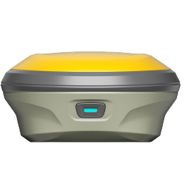 E500
E500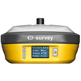 E800
E800 E600
E600 eDMR1
eDMR1 NET10
NET10 NET20 PLUS
 eHP10
eHP10 P9IV
P9IV UT12P
UT12P UT32
UT32 Surpad4.2
 GEOSolution
 GNSS.NET
 eScan M1
 eHLS2
eHLS2 eME30
eME30 eME10
eME10 eMP10
eMP10 eMG30
eMG30 eMR10
eMR10 eMB10
eMB10 eMC10
eMC10 Bestar 301
  EAS301 Pro Motor
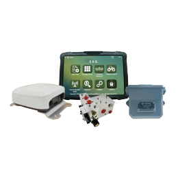 EAS301 Pro Hydraulic
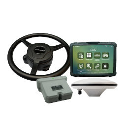 EAS100
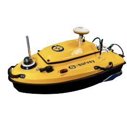 VE115
VE115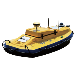 VE158
VE158 E3
E3 eTS2
eTS2 eTS5
eTS5 eTS8
eTS8 ESL2
ESL2 ESL3
ESL3 ET2A
ET2A TRU35
TRU35 UA91
UA91 UA92
UA92 UA35
UA35.png)

